
How I Run MEP Clash Coordination: From Clash Test to RFI to Closure
By Tun Zaw Oo · MEP BIM Coordinator (Fire Protection) · ISO 19650-2 PIM Practitioner (BRE Global)
Clash detection is the part of BIM everyone knows. Running a clash test is easy: Navisworks will happily report thousands of clashes. The skill is in what happens next: setting up tests that produce useful results, deciding which clashes matter, getting them resolved by the right people, and proving it.
This is the coordination workflow I use as a fire protection BIM coordinator on multidisciplinary projects in Singapore, with examples from real projects.
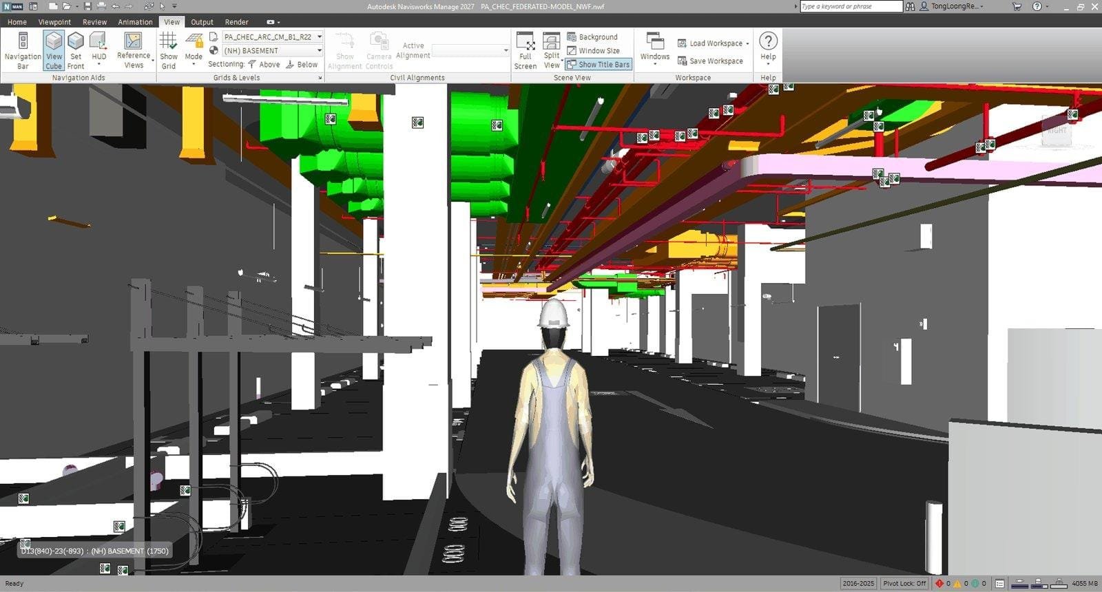
The workflow at a glance
| Step | What happens | Tools |
|---|---|---|
| 1. Requirements | Codes, BEP, naming, service zones and client requirements reviewed | BEP, EIR, design criteria |
| 2. Model development | Discipline model built to project standards | Revit |
| 3. Federation | Architecture, structure and MEP models combined on shared coordinates | Navisworks |
| 4. Clash detection | Search sets, clash rules and tests with tolerances | Navisworks |
| 5. Coordination | Resolutions agreed with architecture, structure and other MEP trades | Coordination meetings, Revizto |
| 6. RFI / issue resolution | Major issues raised as RFIs; replies checked before the model changes | RFI log, Revizto, ACC |
| 7. QA | Model health, parameter and standards checks | QA checklist, Dynamo |
| 8. Information exchange | Shared through the CDE and submitted for authorisation | ACC / BIM 360 / Aconex |
1. Set up tests that produce signal, not noise
A clash test that returns 4,000 results is not information; it’s noise. Before running anything, I make sure:
- Federation is right first. All models are on shared coordinates, and grids and levels align with the architectural model. On an ISO 19650 project I tested federation and ran a trial clash test during mobilisation, before production started.
- Search sets are by system, not just by model. For example: sprinkler mains versus structural beams, sprinkler branches versus ductwork, fire protection versus cable containment.
- Tolerances reflect reality. Hard clashes, plus clearance tests where insulation, maintenance access or installation space matter.
- Tests are grouped by level and zone, so results map directly to the people and drawings responsible.
2. Classify every clash: major or minor?
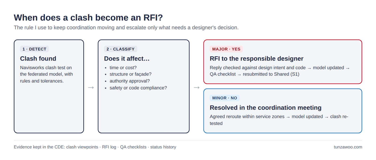
Not every clash deserves an RFI. Escalating everything slows the project down; escalating nothing leaves real risks unresolved. My rule:
- Major: the clash has a time or cost impact, or affects structure, façade, authority approval, safety or code compliance. It goes to the responsible designer or consultant as an RFI.
- Minor: no time or cost impact, and it can be resolved within agreed service zones. It is closed in the coordination meeting and re-tested.
3. Make clashes visible where the design happens
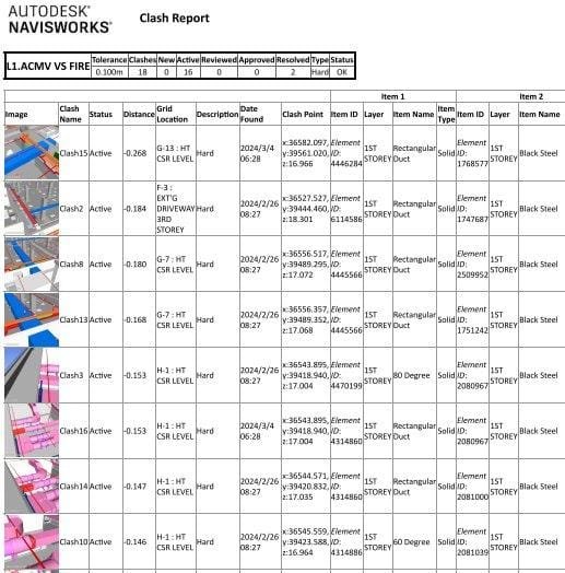
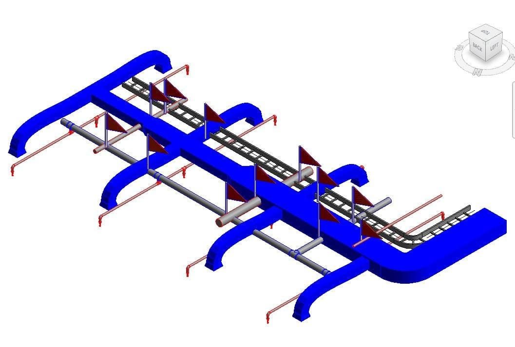
A common coordination failure: the clash report lives in Navisworks, but the designers work in Revit. Each issue must be found again by hand. To close that gap I built a Dynamo tool that reads the Navisworks clash report (XML) and places a flag at each clash point in the Revit model, assigned to the responsible trade team. Issues are then tracked to closure in Revizto.
4. Resolve with engineering, not just geometry
This is where my fire protection background matters most. Moving a sprinkler main to clear a duct is a geometry fix. But if the reroute breaks sprinkler coverage, creates an obstruction, or adds enough pressure loss to fail the hydraulic design, the problem has only moved. Before I accept a reroute I check:
- sprinkler coverage, spacing and obstruction rules
- installation clearance and access to valves and equipment
- hydraulic performance, re-verified in the calculation software when routes or pipe sizes change
Example: Level 2 ceiling void
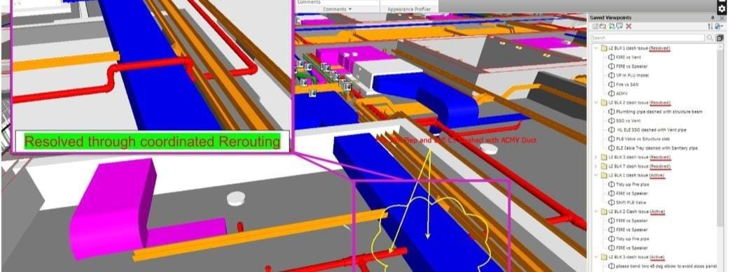
On an assisted living project, the Level 2 ceiling void held sprinkler pipework, ACMV ductwork and cable trays in the same zone. This met the “major” test: RFIs were raised on ACMV duct coordination at Level 2 and on ceiling void clearance, where there was not enough coordination space. After the replies were agreed, services were rerouted within the agreed mounting heights and service zones, and riser and plant space were confirmed with the architect and structural engineer.
Example: congested corridor
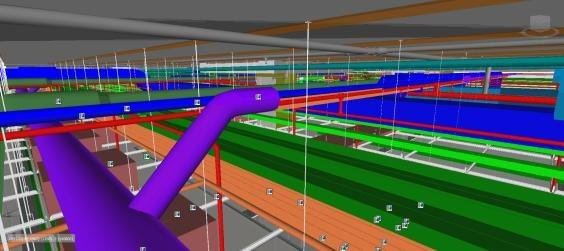
On a four-storey training centre annexe, the corridor ceiling void was one of the most congested areas: ductwork, cable trays and pipework competing for the same space. Fire protection mains were routed around them in the model, and hangers were modelled after coordination so supports were resolved before installation.
5. Close the loop, with evidence
A clash is only resolved when the updated model has been checked and shared. My close-out sequence:
- RFI reply checked against design intent and code
- Model updated in WIP
- Clash re-tested
- QA checklist completed (model health, parameters, standards)
- Model resubmitted to Shared with suitability S1
On one ISO 19650-2 project, four major coordination RFIs were raised and closed this way before the models were submitted for authorisation. The CDE kept the evidence trail: clash viewpoints, the RFI log with consultant replies, completed QA checklists and container status history.
Penetrations: the clashes you prevent
Some of the most valuable coordination happens before a clash test runs. On an industrial cleanroom facility, 303 slab and wall penetrations (94 slab and 209 wall sleeves) were placed and coordinated with the structure in the model. That made openings a planned deliverable instead of site discoveries. Sleeve and opening placement is automated with Dynamo, so it is consistent every time.
What makes coordination work
- Prepare before you test: federation, search sets and tolerances decide whether results are useful.
- Classify ruthlessly: escalate only what needs a designer’s decision.
- Put issues where designers work: in the model, assigned to a team.
- Check the engineering, not just the geometry: a reroute must still meet code and hydraulics.
- Close with evidence: re-test, QA, share, and keep the record in the CDE.
Related: ISO 19650 in MEP: a real task-team case study · BIM Automation: 10 Dynamo tools · Model QA is more than clash detection