
ISO 19650 in MEP: Information Governance Across the Asset Lifecycle
How ISO 19650 principles become structured, auditable information management on MEP projects, with a real case study from my own fire protection task team.
By Tun Zaw Oo · MEP BIM Coordinator (Fire Protection) · ISO 19650-2 PIM Practitioner (BRE Global)
When we talk about BIM in MEP, it is easy to focus on geometry: ductwork, pipework, cable trays and sprinkler mains. But the real power of BIM is not the model itself. It is the information embedded in, attached to and delivered through that model. The ISO 19650 series (BS EN ISO 19650 in the UK) is the international framework for how that information is specified, produced, checked, exchanged and maintained across the life of an asset.
This article explains the key ISO 19650 concepts from an MEP point of view, then shows how I applied them on a live project.
Common Data Environment (CDE)
The CDE is the agreed single source of information for the project: a controlled workspace where every model, drawing and data set lives, with full traceability of who did what, and when.
| State | Purpose |
|---|---|
| Work in Progress | The task team’s authoring area, not visible to others |
| Shared | Checked information shared with other task teams, with a suitability code (e.g. S1 – suitable for coordination) |
| Published | Authorised information for construction or handover |
| Archived | Record of everything shared and published: the audit trail |
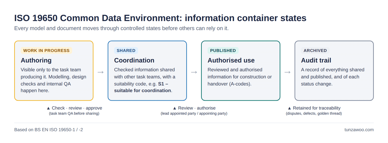
On an MEP project, every HVAC, electrical, plumbing and fire protection model passes through these states before anyone else relies on it. The metadata discipline this requires (naming conventions, status codes, revision histories) is not bureaucracy for its own sake. It is commercial protection: when a dispute arises, the CDE shows exactly what was issued, when, and for what purpose.
Defined information requirements
ISO 19650 defines what information is needed, and why, before a single element is modelled. The client sets out its needs up front, and the delivery team responds in a structured, traceable way.
| Requirement | Question it answers | What it covers |
|---|---|---|
| OIR | WHY is information needed? | The organisation’s strategic reasons and the decisions the information must support |
| AIR | WHAT asset data? | The data needed to operate and maintain the asset: equipment data, maintenance intervals, O&M information |
| PIR | WHAT must the project answer? | The information the client needs for key decisions during design and construction |
| EIR | HOW and WHEN is it delivered? | What each appointed party must deliver: content, format, Level of Information Need, acceptance criteria and dates |
For MEP engineers this hierarchy is very practical. If the AIR says the operator’s CAFM system needs manufacturer, installation date and warranty data for every sprinkler head, that requirement flows through the EIR into each task team’s model. It avoids the familiar situation of a rich model the FM team can’t use.
Information delivery planning: TIDP and MIDP
TIDP (Task Information Delivery Plan): produced by each task team. It lists every information container, who is responsible, formats, delivery dates and dependencies.
MIDP (Master Information Delivery Plan): the lead appointed party combines all TIDPs into one programme-linked master schedule.
Planned properly, each deliverable has an owner, a format and a deadline, and the dependencies between disciplines become visible before they turn into delays. The case study below shows why that matters.
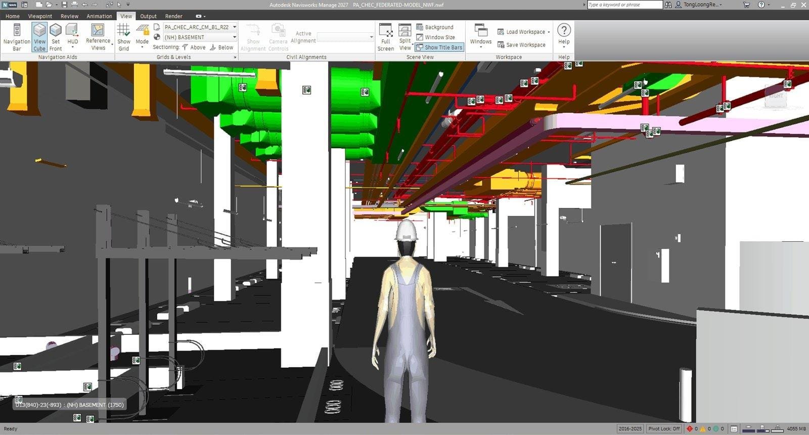
Case study: ISO 19650-2 in a fire protection task team
Project: Parry Avenue Assisted Living Apartment, Singapore (two building blocks)
My role: Fire Protection BIM Coordinator, leading the fire protection task team (1 coordinator + 2 modellers) within the subcontractor scope
CDE: Autodesk Construction Cloud (ACC). The BEP, MIDP and authorisation of information were held by the main contractor as lead appointed party.
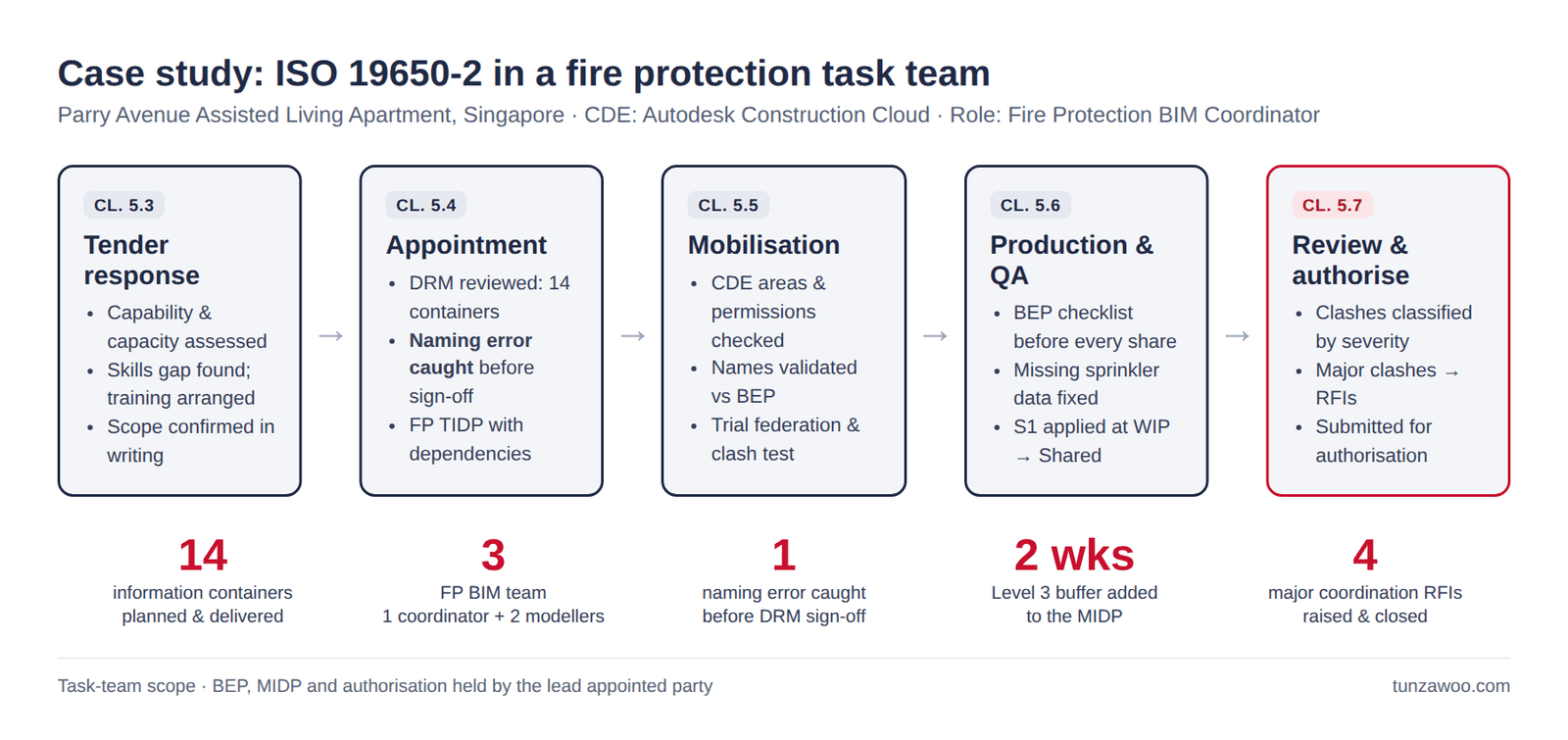
I mapped our work directly to the ISO 19650-2 delivery process:
| ISO 19650-2 stage | What I did |
|---|---|
| Tender response (cl. 5.3) | Assessed our task team’s capability and capacity (5.3.3): people, process and technology against the project information requirements. Identified a skills gap in the WIP-to-Shared workflow and arranged training before the first submission. Confirmed my coordinator scope in writing with the lead appointed party. |
| Appointment (cl. 5.4) | Reviewed the detailed responsibility matrix (5.4.2) and verified all 14 fire protection information containers. Found a naming error (one container recorded as “UR-ALL” instead of separate block references) and had it corrected before sign-off. Prepared the fire protection TIDP (5.4.4) with containers, dates and upstream dependencies. |
| Mobilisation (cl. 5.5) | Checked the ACC WIP/Shared/Published/Archived areas and access permissions against the project CDE workflow. Validated container names against the BEP naming convention. Tested the production methods (5.5.3): federation on project coordinates and a trial clash test before production began. |
| Collaborative production (cl. 5.6) | Completed the BEP model validation checklist before every Shared submission (5.6.3 quality assurance check). Found missing installation-status data on Level 2 sprinklers and corrected it before resubmission. Applied S1 suitability when approving information for sharing (5.6.4). Classified clashes by severity and escalated major ones as RFIs: 4 major coordination RFIs raised and closed before model update. |
| Information model delivery (cl. 5.7) | Submitted our containers for review and authorisation by the lead appointed party (5.7.1–5.7.2), who controlled the Published status in the CDE. |
Managing a delivery risk through the TIDP
Level 3 sprinkler routing depended on structural beam coordination and ceiling clearance, while our three-person team was handling overlapping Level 3–5 submissions. I recorded the dependency in the TIDP and escalated it in writing before the MIDP was finalised. Result: the lead appointed party added a two-week sequencing buffer for Level 3, aligning the structural and fire protection submission windows and reducing rework risk.
From clash to RFI: a worked example
Not every clash needs an RFI. My rule on this project: a clash with a time or cost impact, or one that affects structure, authority approval, safety or code compliance, goes to the responsible designer as an RFI. Minor clashes with no impact are closed in coordination meetings.
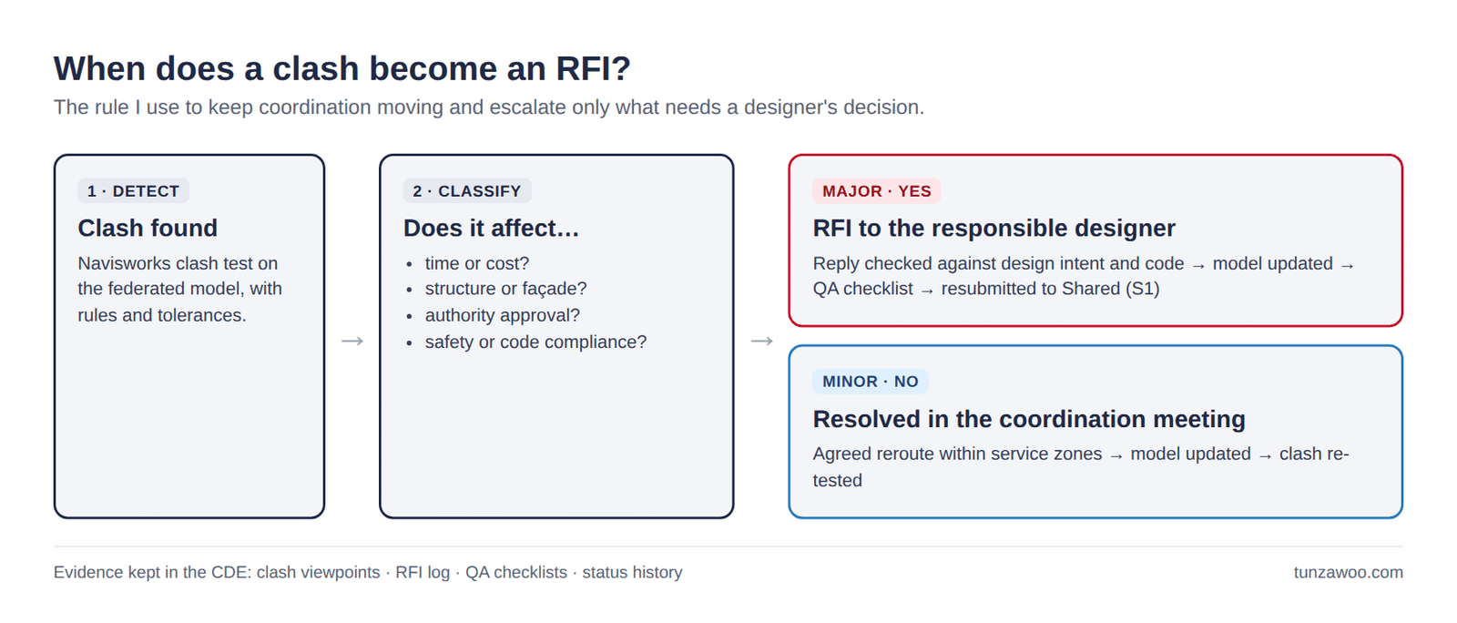
A worked example from the project:
- 30 Apr 2025: RFI raised because the fire hydrant plinth size was missing from the drawings.
- 2 May 2025: the consultant replied with a 1 × 1 m plinth, per the layout plan.
- I checked the reply, then updated the Revit model.
- The QA checklist was passed and the model was resubmitted to Shared (S1).
Every step was recorded in the CDE: clash viewpoints, the RFI log with consultant replies, completed QA checklists and the container status history.
What I learned
- Most information problems are caught at appointment and mobilisation, not in production. The naming error and the Level 3 risk were both resolved before any modelling time was lost.
- A TIDP is a risk tool, not just a list. Writing down dependencies made the Level 3 problem visible to the people who could fix it.
- QA before sharing protects everyone. Missing data caught in WIP costs minutes; the same gap found at handover costs weeks.
Note: on this project, the Level of Information Need was defined by the project delivery requirements as LOD 400-equivalent geometry plus required alphanumeric asset data per container. In UK practice this would be expressed using BS EN ISO 7817-1.
Project to asset model: the critical handover
ISO 19650 separates the Project Information Model (PIM), meaning everything produced during design and construction, from the Asset Information Model (AIM), which the operator needs to run the building: asset registers, maintenance data, O&M manuals, warranties and spares. ISO 19650-2 covers how information is checked and accepted at handover; ISO 19650-3 covers managing the AIM during operation.
For fire protection and other MEP systems, this handover matters for safety as well as efficiency. In the UK, the Building Safety Act 2022 requires a “golden thread” of accurate information for higher-risk buildings, and sprinklers, risers and fire alarm systems are central to it. Structured, verified asset data is how that thread starts.
Why this matters for MEP professionals
- Risk control: defined responsibilities and traceable deliverables reduce disputes.
- Auditability: every revision, approval and exchange is recorded.
- Commercial protection: a clear EIR and MIDP make scope creep visible.
- Lifecycle continuity: information remains usable for FM, refurbishment, ESG reporting and building safety.
Key takeaways
- The CDE is a governed workflow, not file storage.
- OIR → AIR / PIR → EIR: the client’s needs drive what MEP teams model.
- TIDPs and MIDPs turn deliverable lists into accountable, dependency-aware commitments.
- The PIM-to-AIM handover is where lifecycle value is won or lost.
- ISO 19650 parts: -1 concepts, -2 delivery, -3 operation, -4 information exchange, -5 security, -6 health and safety information (2025).
Related: BIM Automation: the Dynamo tools I use for model QA · When BIM Stops at Handover, We All Lose